VMware NSX | L3 Routing | Logical Router | NSX Edge Installation
Topology Diagram:

NSX Edge:
It is the communication between NSX world and physical world.
NSX Edge is a gateway service that provides access to physical and virtual networks for VMs. NSX Edge can be installed as a distributed virtual router or as a services gateway.
It can be used as DHCP server , VPN , Loadbalancer , NAT, Firewall.
Following are the Steps to Install NSX Edge:
Step1:Use Installation Type as Edge Service Gateway. for quick installation you can uncheck "Deploy NSX Edge" if this is checked you need to manually configure each settings.

Step3:Specify the Installation host details. here Im Installing in ESXi Host1 through shared datastore via iSCSI interface.
Step4: Create Internal and uplinks
Internal links are links which are connected to virtual world, with interface ip address: 192.168.10.1/29


Step5: You can enable or disable firewall policies with action as accept or deny.

Final Step: Verify the configuration and click on Finish option to complete the installation

Installation is in Progress:-


Logical Router:
It is the communication within NSX world. via Logical switches.
Following are the Steps to Install NSX Logical Router:

Step2:Specify the Installation host details. here Im Installing in ESXi Host1 through shared datastore via iSCSI interface.

Step3: Create Internal and uplinks
Internal links are links which are connected to virtual world server side, with interface ip address:
a)WEB Servers:172.16.60.0/24 ------------>INTERNAL
b)Windows O.S : 172.16.70.0/24----------->INTERNAL
c)Transit link: 192.168.10.0/29 ----------->UPLINK

Step4: Since we created uplink we can specify default gateway which acts as default route to that ip address. Here our NSX Edge router will be our default gateway.


VERIFICATION:-
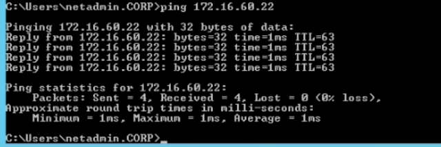
From windows PC(172.16.70.0/24) we are able to ping to fin-web01(172.16.60.20) and fin-db01(172.16.60.22)

ISSUE:
From fin-db01(172.16.60.22) we are able to ping 192.168.10.2 however we are unable to ping 192.168.10.1.


From fin-db01(172.16.60.22) we are able to ping 192.168.10.1 Successfully!!


NSX Edge:
It is the communication between NSX world and physical world.
NSX Edge is a gateway service that provides access to physical and virtual networks for VMs. NSX Edge can be installed as a distributed virtual router or as a services gateway.
It can be used as DHCP server , VPN , Loadbalancer , NAT, Firewall.
Following are the Steps to Install NSX Edge:
Step1:Use Installation Type as Edge Service Gateway. for quick installation you can uncheck "Deploy NSX Edge" if this is checked you need to manually configure each settings.

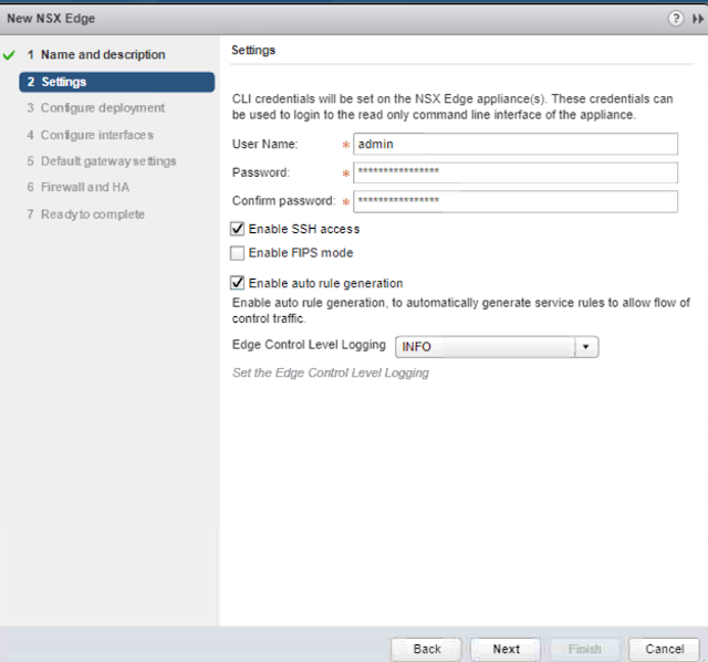
Step2: Create Login credentials, password has to be 12digits. also enable SSH Access to the Edge Router.

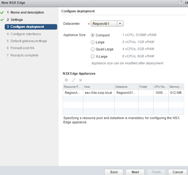
Step3:Specify the Installation host details. here Im Installing in ESXi Host1 through shared datastore via iSCSI interface.

Step4: Create Internal and uplinks
Internal links are links which are connected to virtual world, with interface ip address: 192.168.10.1/29

Step5: Create Uplinks links which are connected to Physical world,

Step5: Since we created uplink we can specify default gateway which acts as default route to that ip address.

Step5: You can enable or disable firewall policies with action as accept or deny.

Final Step: Verify the configuration and click on Finish option to complete the installation

Installation is in Progress:-

Installation Completed:

Logical Router:
It is the communication within NSX world. via Logical switches.
Following are the Steps to Install NSX Logical Router:
Step1:Use Installation Type as Logical Router, for quick installation you can uncheck "Deploy NSX Edge" if this is checked you need to manually configure each settings.

Step2:Specify the Installation host details. here Im Installing in ESXi Host1 through shared datastore via iSCSI interface.

Step3: Create Internal and uplinks
Internal links are links which are connected to virtual world server side, with interface ip address:
a)WEB Servers:172.16.60.0/24 ------------>INTERNAL
b)Windows O.S : 172.16.70.0/24----------->INTERNAL
c)Transit link: 192.168.10.0/29 ----------->UPLINK

Step4: Since we created uplink we can specify default gateway which acts as default route to that ip address. Here our NSX Edge router will be our default gateway.

Final Step: Verify the configuration and click on Finish option to complete the installation

Installation is in Progress:-

Installation Completed: -

VERIFICATION:-
From windows PC(172.16.70.0/24) we are able to ping to fin-web01(172.16.60.20) and fin-db01(172.16.60.22)


ISSUE:
From fin-db01(172.16.60.22) we are able to ping 192.168.10.2 however we are unable to ping 192.168.10.1.

REASON:
There is no return routes(static/dynamic) defined in NSX Edge router pointing towards Logical router.
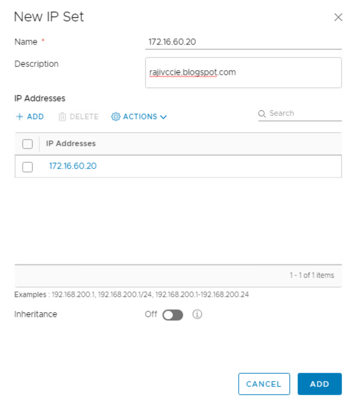
Define static routes in NSX edge pointing towards Logical router as shown below:


